
One question I get a lot is:
I’m using the Vision framework to run an object detection model on iOS but the predicted bounding boxes are not being drawn in the right place. Help!
This is a very common problem and it happens because there are several different coordinate systems that you have to translate between. Which means you need to do math!
In this blog post I’ll explain what’s going on.

Vision and VNRecognizedObjectObservation
Even though most of what I’m about to explain applies even if you’re not using the Vision framework, I’m assuming you’re using Vision to make the predictions and that you have a bunch of VNRecognizedObjectObservation objects that you want to draw on the screen.
Using Vision to get predictions from an object detection model requires only a handful of lines of mostly boilerplate code:
// Tell Core ML to use the Neural Engine if available.
let config = MLModelConfiguration()
config.computeUnits = .all

// Load the Core ML model.
let coreMLModel = try YourModel(configuration: config)

// Create a Vision wrapper for the Core ML model.
let visionModel = try VNCoreMLModel(for: coreMLModel.model)

// Tell Vision which model input receives the image.
// The model may also have additional inputs for the IOU and
// confidence thresholds used by the NMS stage.
visionModel.inputImageFeatureName = "image"

// The request object and its completion handler that gets
// called when the request completes.
let visionRequest = VNCoreMLRequest(model: visionModel) { request, error
  if let results = request.results as? [VNRecognizedObjectObservation] {
    /* do stuff with the observations */
  }
}

// How Vision will resize and/or crop the image data.
request.imageCropAndScaleOption = .scaleFill

// Run the model on an image or CVPixelBuffer.
let handler = VNImageRequestHandler(cvPixelBuffer: pixelBuffer,
                                    orientation: .up)
try handler.perform([visionRequest])
For every detected object, you will receive one VNRecognizedObjectObservation. This gives you the bounding box for the object, as well as any predicted class labels.
The question now is: how to correctly display this bounding box in your app? This is trickier than it may seem!
But this only works if…
Doing object detection with Vision is only possible when the Core ML model has been configured in a particular way.
The model needs to be a pipeline that contains the actual model — such as YOLO or SSD — as well as a special NMS stage that performs non-maximum suppression. You can read more about this in a previous blog post.
Not all Core ML object detection models have already been configured this way, which means you can’t use them with Vision. You either need to turn the model into the kind of pipeline I just described, or write a lot of additional Swift code.
For example, the Ultralytics YOLOv5 model has a Core ML version but it requires changes before you can use it with Vision.
How does Vision treat the image?
It’s useful to understand what actually happens when you give an image to Vision. The options you choose here affect how you should process the bounding boxes afterwards.
Resize and crop
First, Vision will resize the image to the size expected by the model. For YOLO this is typically 416×416 pixels, for SSD it’s something like 300×300 pixels.
Usually your input image is larger than that and it won’t be square.
In this article I’m assuming you’ll be using the iPhone or iPad camera, so your image will likely be 1280×720 pixels or 1920×1080 pixels.
So how do you get a non-square image into a square hole?
Vision lets you do choose an VNImageCropAndScaleOption that determines how the image gets shrunken down to the model’s input size.
centerCrop: Only keep the center square and throw away everything else. For a 1920×1080 image, this means the cropped image will be 1080×1080 pixels. You lose 420 pixels on the left (or top) and 420 pixels on the right (or bottom). Your model won’t be able to detect objects close to the edges of the image because they literally get cut off.
scaleFit: Resize the image but keep the aspect ratio intact. You won’t lose any pixels, but a large part of the input image will now be empty. That’s not very efficient — the neural network will process those unused pixels too — and because of the large scaling factor, the image is bound to lose small details.
scaleFill: Resize the image but ignore the aspect ratio. This keeps the entire image and no pixel goes unused. Unfortunately, the downside is that it will squeeze the image in one direction. For a 1920×1080 image, it will have to fit 1920 pixels in the space of 1080. All the objects in the image will look stretched out now. That’s not a problem if the model was trained on similarly stretched images, but usually it isn’t.
Alternatively, choose a custom crop region by setting regionOfInterest on the VNImageBasedRequest. Of course, you can always do the cropping yourself too.

What is the right option to choose? It depends on your app and also on how the model was trained.
It’s important to remember that what you choose here will affect how you need to transform the bounding boxes later.
The easiest option is scaleFill because then you don’t have to do anything special later on. But it will distort your image if the aspect ratios are very different. With centerCrop, scaleFit, or a custom crop rect, you will have to do additional math afterwards to “uncrop” the bounding boxes.
Note: Apple’s docs for scaleFill are wrong. They say, “scaleFill: A scaling option that scales an image proportionally so that its shorter dimension fills the canvas, potentially cropping along the longer dimension.” But this is the behavior of centerCrop, not scaleFill.
Does it have to be square?
So far I’ve assumed that the Core ML model takes a square input but this is not a requirement!
My advice is to make the input of the Core ML model have an aspect ratio that is close to the aspect ratio of your input images. Then you can just use scaleFill and not worry about the cropping at all.
With many models, such as YOLO and SSD, it’s possible to change the input size without having to re-train the model from scratch, but you might have to change some of the model’s internals too (such as the anchor boxes).
For example, images from the camera will usually have a 16:9 aspect ratio. You might choose a model input size of 352×192 or 384×224, which have a similar aspect ratio. It’s not exactly the same, but close enough. Now scaleFill resizing will not stretch the image — at least not to the extent you’d notice.
Note: For most models the input dimensions must be a multiple of 32, so you may not be able to get the aspect ratio exactly the same.
Is the image in the correct orientation?
Vision also rotates the image, if necessary.
The camera sensor on the iPhone is mounted in landscape orientation, and so if you’re using AVCaptureSession, the CVPixelBuffers are also in landscape. That’s fine if the app is also in landscape mode, but not when it’s in portrait mode.
When the device is in portrait mode, images coming from the camera are seen by the Core ML model as rotated 90 degrees to the right. That’s probably not what the model expects, and it won’t give good predictions!
Because of this, you have to tell Vision what the orientation of the image is, by passing the orientation argument to VNImageRequestHandler. For video frames from AVCaptureSession, this is .right, which tells Vision that it should rotate the image 90 degrees to put it the proper way round.
You can also rotate the image yourself, of course, or set the videoOrientation property of the AVCaptureVideoDataOutput to .portrait. In this case, you don’t need to pass an orientation to Vision, or use the default .up orientation.
Note: If you’re using AVCaptureVideoPreviewLayer to display the live camera feed in your app, that has its own videoOrientation. Just setting that to .portrait is not enough to rotate the actual CVPixelBuffers that are being captured, it only affects the preview layer.
If you’re not using video at all, but regular images, you may still need to handle rotations. Images have EXIF data that contains rotation information that should be passed to Vision as well.
Tip: verify what Vision sees
I wrote a small app for making sure that what Vision sees is indeed what you think it sees. I use this technique all the time for troubleshooting.
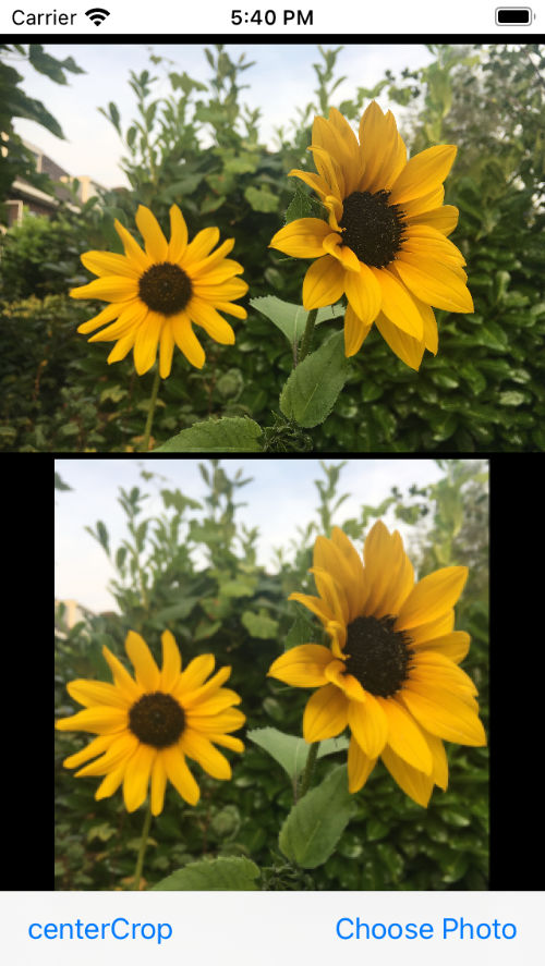
This uses a very simple Core ML model that simply outputs the same image that it was given as input. By drawing the “before” and “after” images, you can see how Vision resizes / crops / rotates the image that gets passed off to Core ML.
The app and model are in the CheckInputImage folder of the Core ML Survival Guide repo. This repo accompanies my book Core ML Survival Guide, which you should definitely buy! 😄
To verify what Vision does to your own images, put the Image2Image.mlmodel into your app and run it instead of your actual model but with the same settings. Grab the output image produced by the model and draw it in a temporary UIImageView. This is literally the same thing Core ML will see when it runs your model.
Note: By default the Image2Image model uses 256×256 images but you can easily change this by editing the create_model.py script. Tip: pay attention to the content mode of the UIImageView. This affects how the image is being displayed, and may therefore be misleading. Make sure the image view is large enough to fit the entire image. Choose “Top Left” for the content mode, so the image does not get scaled by the UIImageView.
How to convert the bounding boxes
At this point, I’m going to assume you set up the Vision crop / scale / orientation options properly, and that you verified the input image that Vision passed off to Core ML is correct for your model. I’m also assuming that the image normalization settings inside the model are good.
Whenever I troubleshoot models for my clients, I always spend a fair bit of time on making 100% sure the inputs are correct. There’s no point in debugging the output of the model until you’ve debugged the input!
The output of an object detection model is an array of bounding boxes. However, you can’t “just” draw these bounding boxes on top of the image.
Because the image that goes into your model is not necessarily the full image due to cropping done by Vision, the coordinates of the predicted bounding boxes don’t “make sense” unless you transform them first.
In addition, because the image and the screen will have different dimensions and aspect ratios, the app is usually not able to display the full image either. The image needs to be resized and/or cropped again to make it fit the screen, and this affects the bounding boxes too.
What makes this tricky is that there are several different coordinate systems that we’re dealing with:
- the full image, before resizing and cropping, e.g. 1920×1080 pixels
- the input image that the Core ML model sees, e.g. 416×416 pixels
- normalized coordinates relative to the crop region
- normalized coordinates relative to the full input image
- the UI view that displays the image and the bounding boxes
Whenever we’re talking about bounding box coordinates, it’s important to understand the reference frame in which these coordinates live.
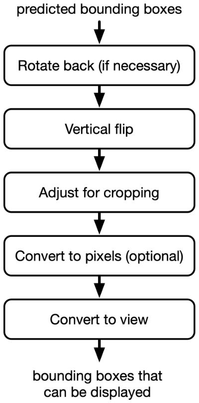
And to get the bounding boxes to show up in the correct place, you need to do a bit of math to convert between these different coordinate systems.
Here is a flowchart of the transformations that are needed:
Vision outputs normalized coordinates
For every detected object, Vision gives you a VNRecognizedObjectObservation. Its superclass, VNDetectedObjectObservation, has a boundingBox property that is a CGRect with the bounding box coordinates of the detected object.
There are a few important things to know about boundingBox:
The coordinates are normalized. This means x, y, width and height are all fractional numbers in between 0.0 and 1.0.
The origin (0,0) is in the lower-left corner! Usually the origin is in the upper-left corner, so that’s a little confusing.
The predictions are relative to the cropped image. In other words, the origin (0,0) is not the lower-left corner of the image but of the crop region.
Finally, if the image was rotated and/or mirrored, then the bounding box coordinates are predicted on that rotated or mirrored image.
You may not be used to dealing with normalized coordinates, but it’s actually quite convenient. It makes the predictions independent of the actual pixel size of the input image. Now we don’t have to worry about Core ML’s coordinate system at all.
Note: Some object detection models don’t use normalized coordinates for their predictions — in which case you can’t use them directly with Vision. For example, if the model works on 416×416 images, the bounding box coordinates will be between 0 and 416. The easiest way to deal with such coordinates is to normalize them afterwards anyway, i.e. divide them by the image’s width and height. This can be done inside the Core ML model.
Un-rotating the bounding boxes
Good news: You don’t need to do this step if you pass the proper orientation to VNImageRequestHandler.
To understand what’s going on here, let’s say the app is in portrait mode and you’ve also set the AVCaptureVideoPreviewLayer to .portrait. You left the orientation of the AVCaptureVideoDataOutput’s AVCaptureConnection as .landscapeRight (the default) and you used orientation: .up in the VNImageRequestHandler.
Because the camera is oriented in landscape, the Core ML model will now see an input image that is rotated by 90 degrees, and so any predictions it makes are rotated by 90 degrees too. (Assuming the model is even capable of detecting objects that are flipped on their side, because that’s how it will see everything.)
To draw these bounding boxes on top of the AVCaptureVideoPreviewLayer, you will have to rotate them back 90 degrees the other way first. Yuck.
A much easier solution is to write VNImageRequestHandler(..., orientation: .right) so that Vision already fixes the image’s rotation before passing it to Core ML. Now Core ML sees the image with the proper side up, the predicted bounding boxes will also be in the correct orientation already, and you don’t need to worry about rotations anymore.
Tip: If your app needs to handle both portrait and landscape, change the orientation of the AVCaptureVideoPreviewLayer upon any device rotations but keep the AVCaptureConnection in landscape always. Pass the UIDevice orientation to VNImageRequestHandler, so Vision knows by how much to rotate the image.
Important: You need to convert the UIDeviceOrientation into something that matches the AVCaptureConnection orientation. For example, if the connection is .landscapeRight and the device is .landscapeLeft (!!!), the Vision orientation should be .up. For some reason, left and right are mixed up here, but this is the natural camera orientation. For device .landscapeRight, the Vision orientation should be .down. If the device is in portrait, the Vision orientation should be .right as explained above.
Fixing Vision’s weird origin
For some reason, Vision’s origin is in the lower-left corner. Usually we want the origin to be in the upper-left, so you’ll need to flip the bounding box vertically.
Because the coordinates are normalized, this is easy enough: make a new CGRect with the y-coordinate at 1 - boundingBox.origin.y. Now (0,0) is in the top-left corner again.
Undoing the cropping
You can skip this section if you used .scaleFill. However, for .centerCrop, .scaleFit, or custom crop rects you will need to do this.
Unfortunately, there is no convenient Vision API that says: “For this mode and this image size, this is the cropping rectangle that was used.” Instead, you’ll have to do this math yourself.
My poor brain finds this easiest to do in the coordinate space of the full image, so that I can work with pixels and whole numbers, but for various reasons it’s smarter to keep everything in normalized coordinates. (Other APIs that we use later on to convert to screen coordinates expect to use normalized coordinates, that’s why.)
At this point, (0,0) is the top-left corner of the crop region and (1,1) is the bottom-right corner of the crop region.
What we want is (0,0) to be the top-left corner of the full image and (1,1) to be the bottom-right corner of the full image.
So we need to convert from the crop rectangle’s coordinate system back to the full image’s. How to do that depends on the imageCropAndScaleOption you chose.
centerCrop
Suppose the full image is landscape 1920×1080 and you used .centerCrop, then Vision cropped out the 1080×1080 square from the center of the image and made its predictions on that.
Expressed in pixels, that means (0,0) from a bounding box really refers to pixel position (420, 0) in the full image and (1,1) refers to pixel position (1500, 1080) in the full image.
Or in normalized coordinates: the top-left corner of the crop region is at (0.22, 0) and the bottom-right corner of the crop region is at (0.78, 1).
If you’re wondering where I got these numbers from: 420/1920 = 0.22 and 1500/1920 = 0.78 (rounded to two decimals).
Therefore, to un-crop the bounding box, we must multiply the predicted width by 0.78 - 0.22 = 0.56 because the crop region’s width is 56% of the full image.
The predicted x-coordinate of the bounding box must also be multiplied by the same amount. This is easy to see if you consider a bounding box with coordinate x = 1.0. This should be at the right edge of the crop region, which is at x = 0.78 in the full image. So scaling down the coordinates is necessary.
We must also add 0.22 to the predicted x-coordinate, because as pointed out above, the crop coordinate (0,0) is located at (0.22, 0) in the full image.
Pseudocode for centerCrop mode, for a landscape image:
let scaleX = fullHeight / fullWidth  // e.g. 1080 / 1920
let offsetX = (1 - scaleX) / 2

var rect = observation.boundingBox
rect.origin.x *= scaleX
rect.size.width *= scaleX
rect.origin.x += offsetX
We don’t have to change the y-coordinate or the height in this example. If the image was in portrait orientation, you’d use a y-offset and scale the height, and leave the x-coordinate and width unchanged.
centerCrop (when crop region is not square)
The above calculation assumes that the input to the Core ML model is square. If not, the math becomes a little more complex. Let’s look at how that works.
In .centerCrop mode, Vision scales the image so that the shortest side fills up the image, while keeping the aspect ratio intact. Then it chops off the excess pixels on the other side.
Let’s say the Core ML model expects a 384×256 input and your image is 1920×1080.
In .centerCrop mode, it first resizes the image so that 1080 becomes 256 pixels.
To keep the aspect ratio intact, the longest side becomes 1920 × 256/1080 = 455 pixels wide. This is wider than 384, so it chops off (455 - 384)/2 = 35.5 pixels on either side to make the resized image exactly 384×256.
NOTE: Since we can’t have half pixels, Vision probably trims 35 pixels off one side and 36 off the other. I have no idea how Vision actually rounds off these fractional values. Since there is no API for getting the crop rectangle, we’re just guessing.
To un-crop the bounding boxes, you have to add those pixels back. Let’s do this in the normalized coordinate space again.
Because 35.5/455 = 0.078 and (35.5 + 384)/455 = 0.922, the top-left corner of the crop region is now at (0.078, 0) and the bottom-right corner is at (0.922, 1).
To un-crop the bounding box, its x-coordinate and width must be multiplied by 0.922 - 0.078 = 0.844 and we must add 0.078 to the x-coordinate.
Pseudocode for centerCrop mode in case the model input is not square, for a landscape image:
// (1080 × 384) / (1920 × 256)
let scaleX = (fullHeight * inputWidth) / (fullWidth * inputHeight)
let offsetX = (1 - scaleX) / 2

var rect = observation.boundingBox
rect.origin.x *= scaleX
rect.size.width *= scaleX
rect.origin.x += offsetX
In portrait, you’d use the y-coordinate and the height instead. The scale factor then is let scaleY = (fullWidth * inputHeight) / (fullHeight * inputWidth).
aspectFit
In .aspectFit mode, the math is different. Vision now resizes the image so that the longest size fits, while keeping the aspect ratio intact. Then it adds padding on the shortest side to fill up the rest of the image.
Let’s again say the Core ML model wants a 384×256 image. Now 1920 pixels becomes 384 pixels. The shortest side, 1080, becomes 1080 × 384/1920 = 216 pixels. That means 256 - 216 = 40 rows at the bottom of the image will be filled with zeros.
Note: These extra rows are wasted. It would have been better to use 384×224 for the model input, which only wastes 8 rows and almost has a 16:9 aspect ratio. Note that 384×216 would make the resized image fit exactly, but it’s not a good choice because 216 does not evenly divide by 32 and many models require this.
The model predicts bounding boxes in the 384×256 image, so (1,1) corresponds to position (384, 256) in this image. But because we only filled in the top 216 rows, we want (1,1) to correspond to position (384, 216).
We’ll need to scale the prediction’s y-coordinate and height by 216/256 = 0.844. There’s no need to add an offset to the y-coordinate.
(Notice how 384/455 from the previous section and 216/256 from this section are both 0.844. That’s no coincidence.)
Pseudocode for aspectFit mode, for a landscape image:
// (1080 × 384) / (1920 × 256)
let scaleY = (fullHeight * inputWidth) / (fullWidth * inputHeight)

var rect = observation.boundingBox
rect.origin.y *= scaleY
rect.size.height *= scaleY
In portrait mode, you’d change the width and x-coordinate instead.
scaleFill
Like I said, you don’t need to do any of this when using .scaleFill. That’s why I prefer using it, because it’s the lazysmart person’s choice.
When using .scaleFill, you do have to make sure the input size used by the model has an aspect ratio that is close to your image’s actual aspect ratio or else the image will get unrealistically stretched and the model’s predictions won’t be great.
Using 384×256 as the model input size — or even better 384×224 — will probably work fine with 1920×1080 images and .scaleFill.
Custom crop rect
If you have a custom crop region, the math is still the mostly the same as above but in two directions instead of just one.
First, calculate where the corner points of the crop region are in the full image, expressed as normalized coordinates. If you used regionOfInterest to set the crop rectangle, you already have this (although it’s flipped vertically).
Once you have the crop region, the horizontal scaling factor is simply the width of the crop region, and the vertical scaling factor is its height.
Then multiply the bounding box’s x-coordinate and width by the horizontal scaling factor; multiply the y-coordinate and height by the vertical scaling factor; and add the crop rect’s top-left corner to the x and y-coordinates.
let cropRect = ...   // normalized coordinates

let scaleX = cropRect.size.width
let scaleY = cropRect.size.height

var rect = observation.boundingBox
rect.origin.x *= scaleX
rect.origin.y *= scaleY
rect.size.width *= scaleX
rect.size.height *= scaleY

rect.origin.x += cropRect.origin.x
rect.origin.y += cropRect.origin.y
Converting to pixel coordinates
You now have the bounding boxes as normalized coordinates relative to the full 1920×1080 input image. The origin (0,0) is in the top-left corner and (1,1) is in the bottom-right corner of that full image.
This isn’t enough yet to display the bounding boxes on the screen — you still need to do the conversion from image to view coordinates (see the next section).
At this point, you may want to leave the bounding boxes in normalized form, or you can convert the normalized coordinates to pixels, so that they are in the coordinate space of your full image.
Which one you should do depends on what API you plan to use for the conversion to view coordinates. Several of these APIs actually want normalized coordinates, in which case you’d skip this step.
Sometimes I find it useful to write a “debug” video that shows the predictions to a movie file, so I can download that movie from the phone and examine it in detail later. In that case, I’d use Core Graphics to draw the bounding boxes directly onto the original video frame and then write the frame to the movie file. It makes sense to have the bounding boxes in pixel coordinates for this.
Let’s say you decide to convert from normalized coordinates to pixels. This is easy enough now that you’ve undone the cropping: just multiply the coordinates by the width and height of the full image. Done!
Vision has a handy VNImageRectForNormalizedRect() function for this.
Note: You may be wondering, if the image is 1920×1080, is the normalized coordinate (1,1) equal to the pixel at (1920, 1080) or (1919, 1079)? Good question. This depends on how you interpret where the center of a pixel is. I don’t worry too much about it — the predicted bounding boxes are not going to be pixel-perfect anyway. No one will notice if you draw them slightly too large or too small.
Converting to view coordinates
Assuming you want to display the bounding boxes on the screen, they will end up in some kind of UIView or CALayer. This view may cover the entire screen, or perhaps it only takes up a small portion.
Regardless of how the results will be displayed, it’s safe to say that the image or camera frame you’re working with will be larger (or smaller) than the number of pixels on the screen. And usually you’ll capture video in a 16:9 or 4:3 aspect ratio but most iOS devices do not have screens in that aspect ratio.
For example, the image may be 1080×1920 pixels (portrait) while your phone’s screen is perhaps 390×844 points. We can’t resize the image 1:1 to fit it into the view — it would look very distorted.
Usually you’d want to resize the video while keeping the aspect ratio intact. This can be done by adding “letterboxing” on the sides of the video or by having some portions of the frame fall outside the visible screen.
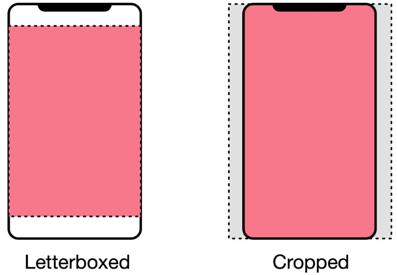
This is very similar to the resizing and cropping that happens when the image gets passed into the Core ML model, except this time it’s for displaying the image on the screen inside a view of some kind.
The bounding box coordinates need to be transformed in the same way. This final translation step turns the (normalized) image coordinates into view coordinates.
There are many options here, depending on what API you’re using to display the images:
If you’re using
AVCaptureVideoPreviewLayer, thevideoGravitydetermines how the pixels from the camera frame are shown on the screen. This is very similar to theimageCropAndScaleOption: there are.resizeAspectand.resizeAspectFillmodes that determine whether the image will fill up the entire screen or whether letterboxing will be added.AVCaptureVideoPreviewLayerhas alayerRectConverted(...)method that can convert normalized coordinates to a rectangle inside the preview layer’s coordinate system.ARKit has its own way to crop and scale the video frames. You can use the method
displayTransform(for:viewportSize:)fromARFrameto compute the transform.If you’re displaying images using
UIImageView, then you have to take itscontentModeinto account. This determines how the image will be scaled and/or cropped, and you need to apply the same rules to your bounding boxes.If you’re using Metal to draw everything, you’ll need to figure out yourself how the textures get placed into the
MTKView.
Once you have converted the bounding boxes to the view’s coordinate system, make sure to add your BoundingBoxView objects as subviews of this view so that they indeed use its coordinate system.
OK, that’s about it. There are quite a few steps involved but I hope it’s clearer now what you need to do to get the bounding boxes to show up in the right place.
Perhaps this blog post makes it look like you need to write tons of math code, but you can usually capture all the operations needed into a single transformation matrix — such as CGAffineTransform — and then apply that to the points of the rectangle.
For an example of how to do that, see the MobileNetV2+SSDLite demo app in the Core ML Survival Guide repo.
Apple has also posted some sample code that you might find useful. Their method updateLayerGeometry computes a CGAffineTransform that scales and rotates the bounding boxes. Worth studying their approach!
Tip: To debug your math, I suggest applying it to a bounding box with normalized coordinates (0,0) and size (1,1). This bounding box should now show up around the borders of your image. Also try boxes of size (0.5, 0.5) placed at (0, 0), (0, 0.5), (0.5, 0) and (0.5, 0.5). If those all appear in the right place, your math is sound.
First published on Wednesday, 25 November 2020.
If you liked this post, say hi on Twitter @mhollemans or LinkedIn.
Find the source code on my GitHub.
 New e-book: Code Your Own Synth Plug-Ins With C++ and JUCE
Interested in how computers make sound? Learn the fundamentals of audio programming by building a fully-featured software synthesizer plug-in, with every step explained in detail. Not too much math, lots of in-depth information! Get the book at Leanpub.com